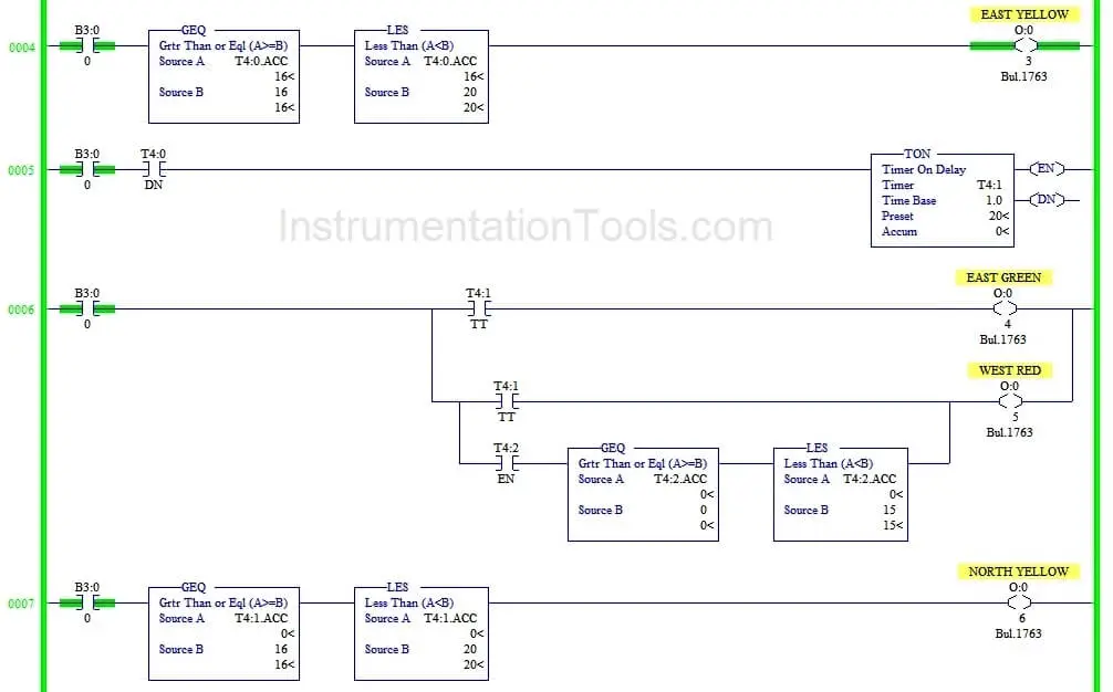
For engineers that are not familiar with relay logic, though, ladder diagrams can be difficult to implement, debug, and maintain, especially when programming complicated machines with state-based behavior. This graphical language mimics a relay logic electrical schematic familiar to electrical technicians.

Ladder diagrams are an industrial programming language typically used on programmable logic controllers (PLC). Review of Ladder Diagrams and Sequential Fuction Charts
Translation Using Higher Level Operations. Translation Using Ladder Diagram Primitives. Review of Ladder Diagrams and Sequential Function Charts. This technique is of particular interested to DMC because many projects we encounter require older or limited hardware platforms. Instead, the program can be designed with a state transition diagram or sequential function chart and then, if a direct method of programming these structures into the PLC is not available, translated into a ladder diagram. Ladder diagrams are available on almost all programmable logic controllers (PLC) but writing large programs with complex state-based behavior in ladder diagrams is cumbersome. This blog describes a procedure for translating a state transition diagram or sequential function chart into a ladder diagram. 
This content was originally published by Eric Anderson as a white paper.


 0 kommentar(er)
